Blueprints
Overview
A blueprint is a digital twin of physical/virtual entities of a system or the whole system itself. Creation of blueprint is a way to replicate an existing physical or virtual entity and perform computataions and analytics over the created digital twins. All the capabilities of altergo's platform begin by creating the blueprint of the system upon which we employ our analytics for a desired outcome. Blueprints are the most fundamental unit of Altergo. They're used to provide context to the data collected by the platform, in asset tracking from manufacturing & assembly to maintenance.
Types
There is no limit to the kinds of blueprints you can create using altergo. There are various pre-defined blueprint categories you can choose from or can opt for or choose Misc. or Other in the category section to create a new type of blueprint.
Properties
Any physical or virtual entity can have different properties which need to be correctly specified as part of its digital twin. All the properties are specified during the blueprint creation process under different sections namely:
-
General: Under this section, you can simply add the name, category and image for the blueprint.
-
Parameters: You can different metrics of the entity e.g. voltage, cost, height, width, power, etc.
-
Properties: These are specific propoerties which vary asset to asset. Since, all the assets pf a company of the same type will share a blueprint. But, if the user want incoporate any changes within the assets they can be specified using the properties section. It has three options text, number and datetime. The text option allows to add any property that is string type. The number option allows to add any numeric property and datetime option allows to specify any particular date.
-
Interface: This section allows you to add sub-components of the existing blueprint. Using this section you can create hierarchical level of architecture for a blueprint by interfacing it with its various subcomponents.
-
Sensors: This section allows you to add any sensor associated with the blueprint. You can add a physical or virtual sensor.
-
Managers: This section allows you to set read or write privileges to different users to a specific blueprint.
Tutorial
In this section, we will look at how to create a blueprint for a photovoltaic battery with the following specifications :
| Parameter | Value |
|---|---|
| Voltage | 21.6V |
| Current | 5A |
| Type | Series Connected Module |
| Power output | 108 W |
Specifications of Sub-component
It will also contain the following subcomponent which needs to be interfaced:
| Subcomponent | No. of subcomponents | Cell Chemistry | Voltage | Current |
|---|---|---|---|---|
| Photovoltaic Cell | 36 | Crystalline Silicon | 0.6V | 5A |
We encourage you to experiment and add more parameters and subcomponents than what this tutorial is proposing
Opening the blueprint builder
.png)
Using the side-menu, go to the following: 1. Digital Twin > 2. Blueprints on the top right of the window click on + 3. Add New Blueprint you'll land in the blueprint builder wizard.
Providing general information

This is the first step of creating a blueprint. To create and save a blueprint, "name" and "category" fields must be filled out. The steps are as follows:
- Name: Choose a relevant name such as a part number, avoid using brands or generic name. It allows you to find your blueprint in the browser easily.
- Category: Choose "Cell module" option since we are creating a blueprint for a photooltaic module.
- Image: This allows to you upload the image of your blueprint. Download an image of photovoltaic module and upload it from your computer.
While not mandatory, attaching an image of your model is recommended to facilitate browsing. Image size shouldn't exceed 200x120 pixels for optimal display
Adding Parameters
Parameters are relevant specification values of the model. In this step, we will provide the parameters related to photovoltaic module specifed above.
Parameters are composed by:
- A Name with an associated unit in S.I(if relevant)
- A set of values with:
- a Prefix [Min,Max,Nom...] (if relevant)
- a Value [number, text]
- a Multiplier [p,n,u...,k,M,G] (if relevant)
| Parameter | Value |
|---|---|
| Voltage | 21.6V |
| Current | 5A |
| Type | Series Connected Module |
| Power output | 108 W |
Add Voltage parameter
- Click on the +Add button in order to create a new parameter. You will see the parameter form appear.
- Click on 1. select parameter model option and type 2. voltage and select it.
- Click on 3. value and add the voltage value 21.6, as provided in the table.

- Repeat the same steps for other parameters: 1. Current, 2. Type and 3. Power Output as shown in the figure.

Creating Blueprint of Photovoltaic Cell
Whenever, we create a blueprint of an entity or a system. We create blurprints of its components indivually and then at the end we interface them together to form a hierarchical structure of the blurprint. Since our blueprint "photovoltaic module" has a sub-component which needs to be interfaced with it. We have to create a blueprint of the subcomponent separately and then interface it with our final bluepint.
Below is the table consisting the information of all the parameters of the sub-component we will input in the blueprint.
| Subcomponent | No. of subcomponents | Cell Chemistry | Voltage | Current |
|---|---|---|---|---|
| Photovoltaic Cell | 36 | Crystalline Silicon | 0.6V | 5A |
Follow the same steps of blueprint creation process as we did before for photovoltaic module.
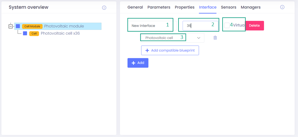
Interface
Interface allows to add any sub-components of the system. The photovoltaic module is composed of 36 photovoltaic cells.
Interface is described by:
- A Name with an associated with a pre-existing model
- A Quantity
- A Virtual state, to describe if the sub-component is physically tracked or mentioned to provide additional context.
Go to Interface and follow the steps as follows:
- Click on 1. Interface name and type any name you like. I have typed "new interface".
- Click on 2. Quantity and type "36" as we have 36 no. of cells in total.
- Click on 3. Select blueprint and add the blueprint of the subcomponent i.e. "photovoltaic cell".
- Incase of a virtual sub-component, user can check the tick mark in the option 4. virtual. But, here in this tutorial we donot have to click on it as this is not a virtual sensor. Leave it blank.
- Now you have successfully interfaced the subcomponents with the photovoltaic module which will reflect in the left hand side of the system overview section.
Now, we have successfully created a basic blueprint with another blueprint interfaced with it. This is how we build blueprints and interface more elements based on the complexity of the final blueprint.
We can add some more parameters to our blueprint if we like like sensors, managing manager privileges, adding properties.
Additional information related to creation of blueprints
In this section, we will explore some other options of blueprint creation not covered in the tutorial. We will see how to create sensors, adding sensors to blueprints, managing read/write privileges etc.
Creating sensors
Sensor creation is covered in this article
The user can only add existing sensors while creating a blueprint. So, In order to add specific sensors to your blueprint, make sure they are created already. Also, all the data which gets ingested into the platform is linked to the sensor and the asset associated with sensor will get its data updated everytime we ingest the data. All the analysis is later performed on the ingested data.
While creating and adding sensors, some parameters are required to be specificed which are explained below:
- The name.
- Unit: It is the unit of measurement of the sensor, e.g. for a temperature sensor, it would be in degree celsius.
- Type: There are 4 basic types of sensors provided and the user can choose from them e.g. SOC, Temperature, Current, and SOH. The default value of this option is "custom" and if the sensor doesnt belong to any of the 4 provided options, this option is applicable.
- Scale: This is the multiple by which the sensor values are multiplied for visualisation and other specific computations. 1 is the scale by default.
not completely sure - Alias: You can specifiy an alternate name to the sensor which will be used while parsing the data ingested to match the right CSV column.
I am adding a "tilt" sensor which has a array size of 2 which has orientation angle and tilt angle as both the array elements. The unit for this sensor is in degrees. To add sensors to your model, follow these steps:
- In the left navigation pane, Click on 1. Digital Twin > 2. Sensors > 3. Add new sensor

-
A new window will open. Specify the 1. name.
-
Specify the 2. type. If the sensor doesnt belong to any of the options, set it as custom.
-
Specify the 3. unit.
-
Leave the 4. scale as default i.e. 1.
-
If required specify the 5. alias otherwise leave it blank.
-
Incase your sensor is virtual, then you can check off this mark. But, in the example provided its not virtual so its left blank.

-
Click on 6. save.
-
You can also make display changes in the 7. trace style section, e.g. selecting the line type, line color, opacity, etc. All these changes would be made when the sensor will be opened in the visualisation tool, we will learn about the visualisation tool later.

Repeat the above steps for all the sensors you need to add.
Adding Sensors to the Blueprint
Before starting make sure you have added the Sensors to your respective blueprint.
- Open the blueprint creation page. In the Search bar type, the name of the model created in this tutorial.
- After specifying the sensor, on the right hand side of the sensor is the option edit. Click on the edit option.
- Go to 1. Sensors
- Click on 2. Add
- Click on 3. select sensor and choose your sensor from the list.
- Click on 4. Array map and specify the array size. Here the "tilt" sensor has size 2. We will specify that.
- Click on the third option and specify the sensor 5. array map. For the tilt sensor it is ["Orientation", "tilt"]
- If the sensor is protected, click on 6. no otherwise click yes.

Array maps
Array mapping is used when the user needs to bundle mutliple sensor values into a single logical sensor
Example
Considering a system with 4 "temperature" sensors. Instead of capturing the data in 4 separate sensors
- Temperature 1
- Temperature 2
- Temperature 3
- Temperature 4
The user create a single "Temperatures" sensor with the following array map:
["Temperature 1","Temperature 2","Temperature 3","Temperature 4"]
The user visualizes the data as follow :

Managers
Managers are peoples from your partner's company that will be able to either read or edit the model you are creating.
You can choose from 2 different types of privileges :
- Read: Can only read the model from the Model browser
- Write: Can Read and Edit the model from the Model browser
Everyone with Write privilege will be able to edit the model.
All your model are available to your company designers.
Let's add someone from your partners as a manager for this model
Adding a model manager
- Click on the +Add button to add a new Manager.
- Click on 2. Select person and search for the name of partner company in the list by typing the first letters.
- Click on 3. Select privileges and select the correct privilege level. If you are unsure choose "Read"

Saving the model
All the changes you have made so far have been automatically saved. You can redo or undo any action if you want to.
Cloning
You can clone an existing model to avoid starting from a blank slate. A good practice is to create model templates to standardize model creation within your organization.
To clone a model:
- While on any page navigate to the model page: Digital Twin > Blueprint
- In the Search bar type, the name of the model created in this tutorial
- After identifying the blueprint you want to clone, there is an option on the right-hand side Clone, click on it.
- A blueprint edit page will open with all the information displayed. You can edit all the parameters, category, image and the name of the existing blueprint to create a new one out of it.
- Click on Submit and your new blueprint wil be saved.